Motor Project # 5 - Changing Plugs
 on the X engine are metric), I'll only list parts and special items.
If you follow my process, you'll need the following (all shown in pic):
on the X engine are metric), I'll only list parts and special items.
If you follow my process, you'll need the following (all shown in pic):
- Set (6) upper intake manifold gaskets.
- One throttle body gasket.
- Set (6) spark plugs of your choice.
- Anti-seize compound
- Two pieces of cardboard 2"x12"
- One piece 6" (approx) of 3/8 id fuel line.
I won't get in to discussions about spark plug types. My own opinion - I'm not one for exotic plugs and I only like using what the manufacturer put in from the factory. So, it's your choice. The plugs in my 3.0L engine are a factory #, and appear to be autolite and are definitely a platinum plug. JTIS specifies part # XW4E12405. Autolite's cross over double platinum plug number is: APP605. JTIS gap specification is 0.051" to 0.057".
The gaskets that I've specified are recommended in JTIS to be replaced if they are removed. The 6" piece of fuel line is a special tool that you will use to install the new plugs (very important!). The two pieces of cardboard are like insurance policies. You'll use them to protect your precious engine against yourself - more to come.
OK - Let's begin at the beginning. If you open your hood and stand in front at the grille, your project should lay before you and look something like the picture here. If your engine looks substantially different than the picture, then you're working on the wrong car!
Of course we will be removing three plugs each on two engine banks. The front bank (left bank) is right in front of you. One of the three plugs can barely be seen to the left of the air cleaner. The other three are located in the back bank (right bank) located underneath the intake manifold and close to the firewall - and NO there are no shortcuts, the intake manifold must be removed to get to those plugs. So, let's begin:
- JTIS recommends disconnecting the battery. This is a good idea whenever you are unplugging connections to the ECM and we'll be doing that here.
- Remove the entire air cleaner. The cover, the filter and the lower box. Hardware should be intuitively obvious.
- Remove the ribbed rubber hose connector to the throttle body. Disconnect only one end, the throttle body end, and leave the air filter end fastened.
- Remove the black plastic air baffle past the air cleaner.
- Remove the Positive Crankcase Vent tube that connects the air filter to the intake manifold (just slips off the intake manifold).
- Now the front (left bank) three plug coils should be exposed.
- Continue removing the the intake manifold by removing the sensor connectors to the (2) tuning valves and the (1) manifold absolute pressure sensor. Look at the
 picture of the manifold here. This pic shows the black tuning valves on the far right. The manifold pressure sensor is the black sensor shown on the lower intake rail closer to the tuning valves. All three of these connectors use a timing tooth so they cannot be plugged in backwards. The all have release tabs that must be be pinched to remove.
 - Now let's remove vacuum connections. There are three. Use the same photo and note the two holes, one on the lower rail and one at the junction of upper and lower rail. These connections can be removed by pressing down on the retaining ring then lifting the vacuum hose out. If you're at all in doubt about how to remove these, DO NOT force them. Instead disconnect the other ends. One is the vacuum feed to the power brake. The other hose has a convenient connector with press/release tabs much like the electrical connectors.
- That takes care of two of the three vacuum lines, now for the third. It is located on the back of the intake manifold and cannot be seen. In fact this line and four hardware screws must be
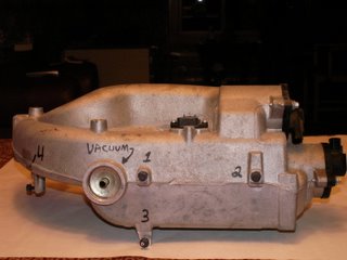 removed (and replaced) using tactile skills. Use the picture here. It is a photo of the back of the manifold. See the fitting position marked VACUUM.
 - Now let's remove or loosen the blind hardware. There are four hex head screws numbered in the picture. All take a 10mm hex socket or box wrench. The first two numbered #1 and #2 simply hold the RH main ECM harness branch in place. These two screws only need to be LOOSENED not removed as the holes in the harness bracket are open slotted. Screws #3 & #4 must be removed completely. They are mounting tabs. #3 cannot be seen, #4 can be seen just below and behind the throttle body.
- Now remove the four bolts (10mm hex socket) that hold the throttle body on to the intake manifold. You will mechanically disconnect the throttle body, but not disconnect any other electrical or coolant connections. The throttle body will just float in position when you remove the intake manifold. By doing it this way, you save several steps e.g.: draining the radiator, removing coolant lines to the throttle body, etc. NOTE/CAUTION: Do not attempt to clean the throttle body. The bore and the throttle plate have a special coating applied during manufacture which should not be removed.
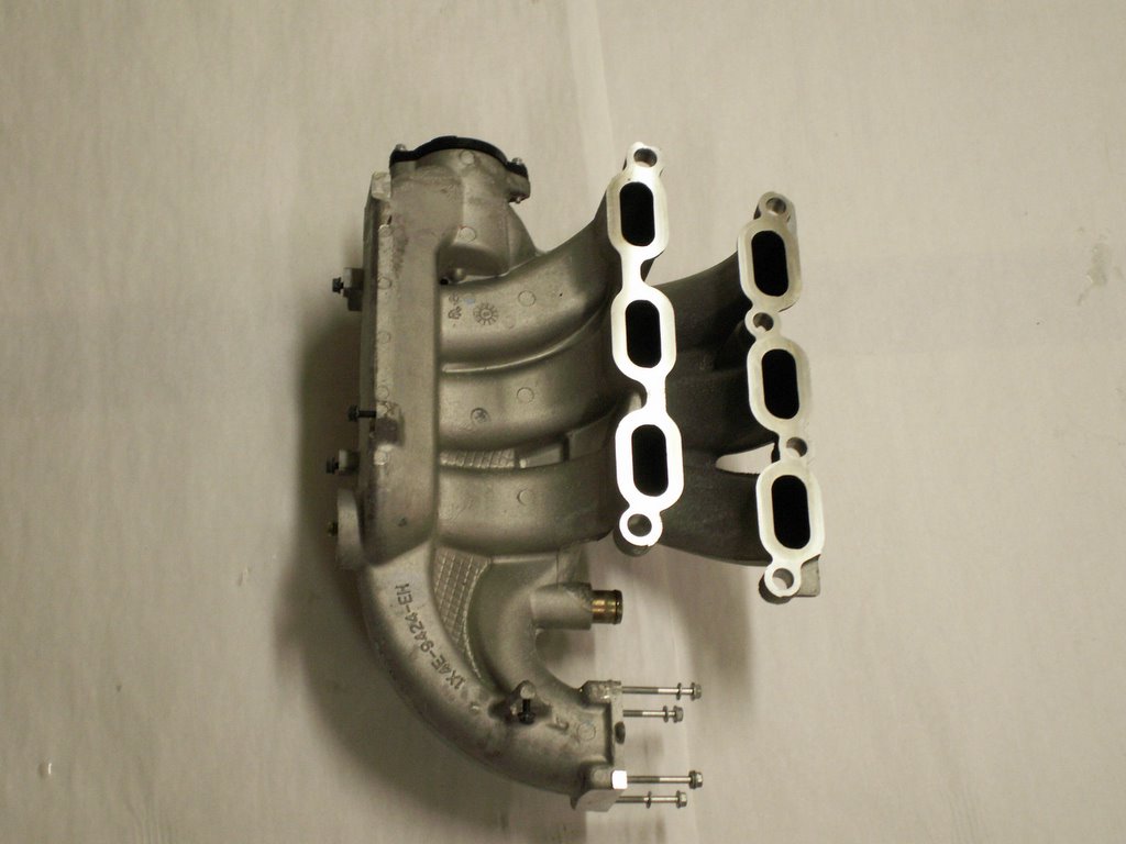
- Now, let's remove the final six hex head bolts that hold the intake manifold in pl
 ace. Look at the pic here and you'll see the manifold upside down and the six mounting positions will be obvious. It is IMPORTANT that you keep all six (6) bolts and rubber washers in their original orientation as they are different lengths and shapes.
 - Once the intake manifold is removed, the lower intake manifold (with the six yellow neoprene intake gaskets) will be exposed. This is a dangerous time because if anything is dropped in an intake port, then you have a whole lot more work to do and not covered in this procedure. As a precaution, use the two precut pieces of cardboard to cover the intake ports as you begin to remove/replace coils and plugs. I've provided a picture of the lower intake port off the engine with one of the two
 cardboard pieces in place. You will NOT be removing this lower manifold.
 - Now all six plug/coils are exposed so the plugs can be changed.
- Each coil is held in place with a hex head screw. Remove the screw, unplug the coil and remove it using a gentle twisting motion.
- It is IMPORTANT that you work in extreme cleanliness at this point. There are no flushing channels anywhere in the plug socket and you want to make sure that no debris of any kind gets in to the plug wells. They should be clean as they are protected by the coil seals. I still use a household vacuum cleaner with hose attachment and suck out anything out from all six wells before removing the spark plugs.
- After cleaning, use a 5/8 spark plug socket (with a rubber insert) on a 3/8 drive extension/ratchet and remove each plug.
- With all of the plugs out, it is a good practice to take note of the burn evidence on each plug. Lots can be told from this. I won't cover it here, but a quick web search can produce colored charts of different burn patterns with explanations.
- Now prepare the new plugs. Check the gap against the 0.051" to 0.057" gap requirement. The Autolite plugs should be correct already. It is a good practice to lean towards the lower measurement. In fact, Autolite specs say the APP605 comes with a 0.050 gap. That is good and I'd leave it as plug gaps will widen as they wear.
- This is where you'll use the anti-seize compound. Place a SMALL amount on the thread body of each plug and distribute around the circumference. Anti-seize compound is important wherever dissimilar metals (aluminum and steel) come into contact. Different metals can actually cold weld together over time because of chemical reaction. If you've had a frozen alloy wheel to your steel wheel hub, then you know what I mean. BTW - I use anti-seize compound of my wheel hubs too.
- Now take the 6" piece of 3/8" id fuel line and force it over the porcelain tip of the first plug. This hose is a special installation tool as your spark plug socket will not release when you install the plug.
- Use the hose with spark plug attached and hand thread the new plug in place (times 6). Then take a 5/8 spark plug socket with the rubber core OUT!! and tighten each plug to 11 ft. lbs.
- From here on, all is replace/reinstall. First place all six coils back in position and fix with their mounting screws. Plug in all six coils to their respective harness connections.
- Next replace the six intake manifold gaskets with new ones. Also replace the blue neoprene gasket for the throttle body located in the intake manifold.
- Install the intake manifold. There is a tightening sequence that is important to follow. I'll diagram it below. Also, first HAND tighten each of the six bolts, in proper sequence, then snug with a 8mm socket/ratchet in sequence, then finally torque to 10 nm (89 in.lbs) in sequence.
- Here is the tightening diagram. Use it as you are standing in front of the car at the grille. The front row has four bolts, the back row has two. Each # is placed on the bolt position. Start with #1, finish with bolt #6.


___5______________________3
_______2____ 1____4____ 6
27. After the manifold is in place with the six primary bolts tightened to torque spec, then complete the assembly of the four screws in the blind spot, (2 hold the harness, 2 are mounting tabs).
28. Reconnect the electrical connectors, (2 to the tuning valves, 1 to the vacuum sensor), then reconnect the vacuum lines, (1 in the back, 2 on top) of the intake manifold.
29. Now remount the throttle body. Four (4) bolts using a 10mm hex socket. These are torqued to 10 nm (89 in.lbs.)
30. Everything past this point is accessory assembly (air cleaner, connections, PCV hose, battery connect, etc).
And that should do it! Simple. If you have any questions, use this forum for Q&A
In a future project posting I'll put the process together to change oxygen sensors (4 in total). In modern OBD II engine design, no other component plays a bigger role in engine performance, gas mileage, etc. than the O2 sensors. Today, these have fairly good extended lives; however, they do deteriorate over time, and some fail. I replace these in my own cars at 60,000 miles.
Enjoy!
posted by skhannes at 7:26 AM
![]()
![]()

0 Comments:
Post a Comment
<< Home